 English

Views: 0 Author: Site Editor Publish Time: 2026-11-04 Origin: Site


Selecting the wrong lens for your laser system creates costly operational bottlenecks. You might experience inconsistent marking depth, poor edge resolution, or excessively long cycle times. A laser marker’s precision relies heavily on the intricate optical relationship between the scanning galvanometer and the focusing lens. If you misunderstand this dynamic, you risk compromising the quality of your entire production run.
The right optics ensure consistent thermal transfer to your material. When engineers ignore optical physics, they often compensate by pushing laser power too high. This accelerates hardware degradation and causes localized heat damage to sensitive components. This article provides engineers and decision-makers with a clear technical evaluation framework. We will explore how to balance spot size, scan field, and energy density based on your exact application requirements. By mastering these variables, you can optimize both processing speed and marking precision, ensuring your equipment performs at its absolute best.
Direct Correlation: A longer F-theta lens focal length produces a larger scan area but directly increases the laser marking lens spot size.
Energy Density Trade-off: Doubling the focal length roughly quadruples the spot area, significantly reducing the energy density (fluence) applied to the substrate.
The Golden Rule of Selection: Always specify the shortest possible focal length that accommodates your required laser marking scan field size and working distance to maximize precision and processing speed.
System Dependencies: Real-world spot size is not solely dependent on the lens; it requires factoring in input beam diameter and beam quality ($M^2$).
Traditional optical systems rely on standard spherical lenses. These lenses focus light onto a curved surface. When a laser beam sweeps across a flat plane through a spherical lens, the image height equals the focal length multiplied by the tangent of the deflection angle ($f \cdot \tan(\theta)$). This geometry creates a severe pincushion distortion. The beam travels further to reach the edges than the center, causing the spot to lose focus.
F-Theta lenses solve this problem through specialized multi-element designs. They manipulate the beam so it focuses evenly across a completely flat plane. In this corrected system, the image displacement is directly proportional to the deflection angle ($f \cdot \theta$). This linear relationship eliminates pincushion distortion. It ensures the beam travels at a constant speed across the target surface. Selecting the proper F-theta lens focal length remains the most critical hardware decision you will make before commissioning a system.
Understanding theoretical spot size requires a brief look at the foundational physics governing laser optics. Engineers use a standard diffraction-limited equation to predict the focal point size.
The equation is: $d \approx 1.27 \cdot \lambda \cdot f / D$
$\lambda$ (Laser Wavelength): The physical property of the light. A 355nm UV laser naturally produces a smaller footprint than a 1064nm fiber laser.
$f$ (Focal Length): The distance from the optical center of the lens to the focal plane.
$D$ (Input Beam Diameter): The size of the laser beam as it enters the lens assembly, often expanded by an upstream collimator.
This mathematical model shows an inescapable truth. If you increase the focal length, you mathematically increase the beam diameter at the target. Conversely, expanding the input beam ($D$) shrinks the final point, assuming the lens aperture can handle the larger input.
Theoretical limits look great on paper. However, industrial environments rarely achieve these perfect calculations. Several physical variables alter the actual results on your factory floor.
First, thermal lensing distorts optical pathways. High-power continuous processing heats the internal glass elements. This heat slightly changes the refractive index of the material, shifting the focus point mid-cycle. Second, galvanometer mirror tolerances introduce micro-deviations. Finally, industrial lasers rarely possess perfect beam quality. The $M^2$ factor measures how close a beam is to a perfect Gaussian shape. An $M^2$ value greater than 1 means the beam diverges faster than theory predicts. You must always account for these realities during system design.
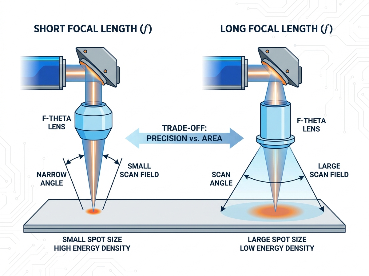
Optical design demands compromise. You cannot buy a lens that provides an infinitely small focal point across an infinitely large area. The relationship between focal length and processing area is strictly proportional. A 160mm lens typically provides a 110mm x 110mm area. Upgrading to a 254mm lens expands that area to 175mm x 175mm. While the larger footprint seems advantageous, it triggers a chain reaction of optical changes.
When you expand the coverage area, you inherently degrade fine detail capabilities. A wider coverage requires a longer focal length, which inflates the final beam diameter. An oversized laser marking lens spot size destroys micro-text legibility. Complex geometries blur together. High-density 2D matrix barcodes suffer the most. If the footprint exceeds the required module size of the barcode, the dark and light cells blend. This causes catastrophic failure during machine vision grading processes. You must match the optical resolution to your finest required detail.
Energy density dictates how aggressively the laser interacts with the material. Fluence follows the inverse square law. When you increase the focal length, the focal point grows. If the diameter doubles, the total area quadruples. Because the laser outputs the same total power, that power now spreads across an area four times larger.
Consider a practical scenario. You upgrade from a 160mm to a 254mm focal length to engrave larger nameplates. Your marking area increases beautifully. However, your peak power plummets. To achieve the previous engraving depth, you face difficult choices. You must either slow down the scanning speed significantly, which ruins throughput, or purchase a much higher wattage laser source.
Despite the drawbacks, longer lenses offer a hidden advantage for edge consistency. When a beam sweeps to the extreme corners of a large area, it strikes the material at an angle. Shorter lenses create aggressive impact angles at the edges, distorting the beam into an oval. Longer focal lengths flatten this trajectory. They deliver the beam closer to perpendicular, even at the perimeters of a large laser marking scan field size. This provides better uniformity for surface oxidation or polymer color-change applications.
Many operators confuse focal length with working distance. They are related but distinctly different measurements. Working distance represents the actual physical clearance between the bottom of the lens housing and the target material surface. It dictates how much room you have to maneuver parts underneath the scan head.
Shorter focal lengths severely restrict mechanical clearance. A 100mm lens might offer incredible energy density, but its working distance might only be 70mm to 80mm. This tight clearance creates collision risks. If you process 3D parts, bulky fixturing, or clamped assemblies, the scan head might crash into the tooling. You must verify physical constraints before prioritizing optical power.
Depth of focus defines the vertical range where the beam remains tight enough to process material effectively. Known in optical physics as the Rayleigh length, this measurement is crucial for non-flat objects.
Longer focal lengths provide a much deeper depth of focus. This deep vertical tolerance proves invaluable in specific implementation scenarios:
Cylindrical Processing: Marking tubes or curved parts without a rotary indexer relies entirely on depth of focus to maintain line thickness as the surface curves away.
Warped Substrates: Processing stamped metals or molded plastics with natural surface deviations requires a forgiving focal plane.
High-Speed Tolerances: Conveyor-belt applications where part height fluctuates slightly demand a deep focal tolerance to prevent random quality drops.
Selecting the right optic requires aligning physical laws with your specific manufacturing goals. Different processes demand radically different optical setups. Deep engraving into tool steel prioritizes brutal energy density over large coverage. Conversely, surface annealing large medical trays demands wide coverage and gentle thermal transfer.
Application-Driven Lens Decision Matrix
Application Type | Suggested Focal Length Range | Primary Benefit | Main Trade-Off |
|---|---|---|---|
Deep Engraving / Metal Cutting | 100mm - 160mm | Maximum energy density; rapid material removal. | Small coverage area; tight mechanical clearance. |
High-Resolution Micro-Machining | 50mm - 100mm | Ultra-fine resolution for micro-text and barcodes. | Extremely short depth of focus; requires flat parts. |
Standard Polymer Marking | 160mm - 254mm | Balanced throughput and contrast generation. | Average energy density; struggles with deep metal cuts. |
Large-Format Surface Annealing | 254mm - 420mm | Processes massive parts without mechanical indexing. | Low peak power; large minimum footprint size. |
Do not order a lens simply based on its dimensions. You must verify internal system compatibility. First, confirm the anti-reflective coating matches your laser wavelength. A 1064nm lens on a 10.6µm CO2 system will block the beam completely, overheating and potentially shattering the glass. Second, evaluate the input aperture. The lens entry diameter must easily accommodate the beam exiting your expander. If the beam is too large, you risk severe vignetting.
Vignetting occurs when the input beam diameter exceeds the clear aperture of the F-Theta lens. The internal housing physically clips the outer edges of the beam. This leads to immediate and severe power loss at the workpiece. More insidiously, vignetting destroys the Gaussian profile of the laser. You will notice distorted edges, hazy halos around engraved lines, and inconsistent processing depth. Always ensure your beam expander ratio matches the lens input specifications.
Field engineers frequently encounter spot distortion at the far corners of the processing area. The circular beam morphs into a stretched ellipse. This causes directional bias. Vertical lines might appear thicker and shallower than horizontal lines. This usually stems from two issues. You might be using budget-tier optics lacking proper flat-field correction elements. Alternatively, the scan head might suffer from physical misalignment relative to the optical axis. Upgrading to a premium telecentric lens often cures extreme edge distortion by forcing the beam to strike the material perpendicularly.
The space between the lens and the material acts as a volatile micro-environment. Short focal lengths place expensive glass perilously close to the ablation zone. Plasma plumes, metal dust, and vaporized polymers rush upward during processing. If this debris settles on the anti-reflective coating, the lens begins absorbing laser energy instead of transmitting it. This triggers rapid thermal failure. For short working distance setups, you must install targeted air-knives or positive pressure nozzles to sweep debris away from the optical path.
Selecting the ideal optical configuration remains an exercise in strategic compromise. You must carefully balance the desire for pinpoint precision against the need for high-throughput area coverage. Understanding the physics behind these optics prevents costly design errors and protects your production timelines.
Never over-spec your scan area "just in case." Buying a massive lens for a small part permanently handicaps your system's energy density. It forces your laser to work harder than necessary, accelerating component wear and artificially limiting your line speeds. Define your largest required part and buy the smallest lens capable of covering it.
Your next step should involve a technical consultation. Gather your material specifications, required cycle times, and exact dimensions. Present this data to your systems integrator or optics supplier. They can process these variables through proprietary optical software to deliver a mathematically validated recommendation.
A: Yes, you can easily swap lenses. However, it requires software reconfiguration. You must update the calibration file (often called a corfile) to correct distortion for the new geometry. You also must physically adjust the Z-axis height to find the new focal plane.
A: Generally, yes. A shorter lens increases fluence, driving more heat into the metal to generate darker oxidation. However, mark darkness also heavily depends on pulse duration, frequency, and scanning speed working in tandem with the optical intensity.
A: This results from optical astigmatism. When the beam deflects at extreme angles, it encounters the glass asymmetrically. Lower-tier lenses fail to maintain rigorous flat-field correction at these extremes, causing the beam to stretch into an ellipse.
A: You cannot calculate working distance using a universal formula. It relies heavily on the internal physical design of the specific lens housing. It typically measures 10mm to 20mm shorter than the nominal focal length. Always consult the manufacturer's exact datasheet.
