 English

Views: 0 Author: Site Editor Publish Time: 2026-11-03 Origin: Site


Transitioning from mechanical to laser glass drilling eliminates drill bit wear and macroscopic fractures. However, engineers still face two critical yield-limiting defects: heat-induced microcracks and geometrical hole taper. These hidden flaws silently jeopardize entire production runs.
In high-tolerance industries like semiconductor packaging, medical devices, and display panels, precision remains non-negotiable. Even micron-level subsurface damage severely compromises substrate strength. Meanwhile, excessive taper prevents proper via metallization or hermetic sealing. By mastering these variables, manufacturing teams can secure reliable performance and scale operations efficiently.
This guide examines the physical causes of these pervasive defects. We evaluate the specific laser parameters, optical beam delivery methods, and inspection protocols required to eliminate them. You will learn how to deploy these proven strategies directly into a high-volume production environment.
Cold Ablation is Mandatory for Zero-Defect Edges: Shifting from nanosecond to ultrafast (picosecond/femtosecond) lasers minimizes the Heat Affected Zone (HAZ), fundamentally preventing thermal stress microcracks.
Optics Control Geometry: Utilizing Bessel beams or specific trepanning optics transforms standard V-shaped tapers into precise, vertical sidewalls.
Yield vs. Throughput Tradeoff: Achieving zero microcracks often requires lower pulse energies and higher repetition rates, requiring careful Total Cost of Ownership (TCO) calculation.
Verification is Critical: Standard optical microscopy is insufficient; rigorous laser drilling glass quality inspection requires cross-sectional analysis and 4-point bend testing to verify subsurface integrity.
You must understand the underlying physics before you can optimize a laser process. Flaws emerge from specific thermal and optical interactions during ablation. Defining these mechanisms establishes clear engineering parameters.
Thermal damage begins within the Heat Affected Zone (HAZ). Materials possess an inherent electron-phonon relaxation time. This metric describes how quickly energy transfers from excited electrons to the atomic lattice. In glass, this relaxation happens in picoseconds. If your laser pulse lasts longer than this threshold, excess thermal energy inevitably diffuses into the surrounding matrix.
This diffusion causes localized rapid expansion. The surrounding cold glass resists this expansion, generating immense mechanical stress. When stress exceeds the material's tensile limits, internal fractures form. Preventing these laser glass drilling microcracks requires keeping pulse durations shorter than the thermal diffusion cycle.
Standard Gaussian laser beams naturally create conical holes. Lenses focus the beam into an hourglass shape. The narrowest point is the beam waist. Surrounding this waist is the Rayleigh range, where intensity remains high enough for ablation. As the beam penetrates deeper, it diverges and loses energy density.
Plasma shielding worsens this geometrical issue. The initial pulse vaporizes the surface, creating an opaque plasma plume. This plume physically blocks trailing photons from reaching the hole bottom. Ablation efficiency drops significantly as depth increases. Consequently, the exit diameter becomes much narrower than the entrance, creating a V-shaped profile.
Engineers must define acceptable defect thresholds based on the end-use application. Generic specifications often fail in high-reliability environments.
Through-Glass Vias (TGV): Require strict tolerances. HAZ must remain under 2µm. Taper angles cannot exceed 0.5 degrees to allow uniform copper plating.
Display Cover Glass: Tolerates slightly broader margins. HAZ under 5µm is often acceptable. Edge chipping must remain invisible to the naked eye.
Medical Microfluidics: Demand absolute edge smoothness. Roughness (Ra) should stay below 1µm to prevent fluid turbulence.
Pulse duration dictates the fundamental interaction between laser light and glass. Choosing the right emission regime separates high-yield production from constant scrap generation.
Traditional lasers rely entirely on thermal processing. They heat the glass until it melts or boils away. These systems are highly economical and operate at incredible speeds. However, they carry a tremendous risk of structural damage. Melt-expulsion inevitably leaves a massive HAZ.
Manufacturers using these systems face a steep tradeoff. You must typically perform post-process chemical etching. Hydrofluoric acid baths dissolve the damaged layers to restore acceptable glass strength. This adds hazardous chemical handling to your workflow.
Ultrafast lasers operate through cold ablation. They deliver photons so rapidly they strip electrons directly from atoms. This process drives multi-photon absorption. The material vaporizes instantly, turning into plasma before heat can physically diffuse into the surrounding glass lattice.
Cold ablation leaves the adjacent substrate entirely untouched. Edges appear polished directly off the machine. This fundamental shift eliminates thermal stress entirely.
Femtosecond lasers offer the absolute lowest risk for subsurface defects. They represent the gold standard for aerospace and semiconductor packaging. However, they carry a significantly higher capital expenditure compared to other options.
Picosecond systems often provide the ideal commercial sweet spot. They deliver cold ablation benefits but require less complex internal optics. Many display manufacturers standardize on picosecond sources for reliable daily operations.
Laser Processing Parameter Comparison
Laser Regime | Typical Pulse Duration | Primary Ablation Mechanism | Microcrack Risk Level |
|---|---|---|---|
CO2 / Nanosecond | > 1 ns | Thermal Melt & Expulsion | High (Requires Etching) |
Picosecond | 1 - 100 ps | Cold Ablation / Multi-photon | Low |
Femtosecond | < 1 ps | Pure Cold Ablation | Minimal to None |
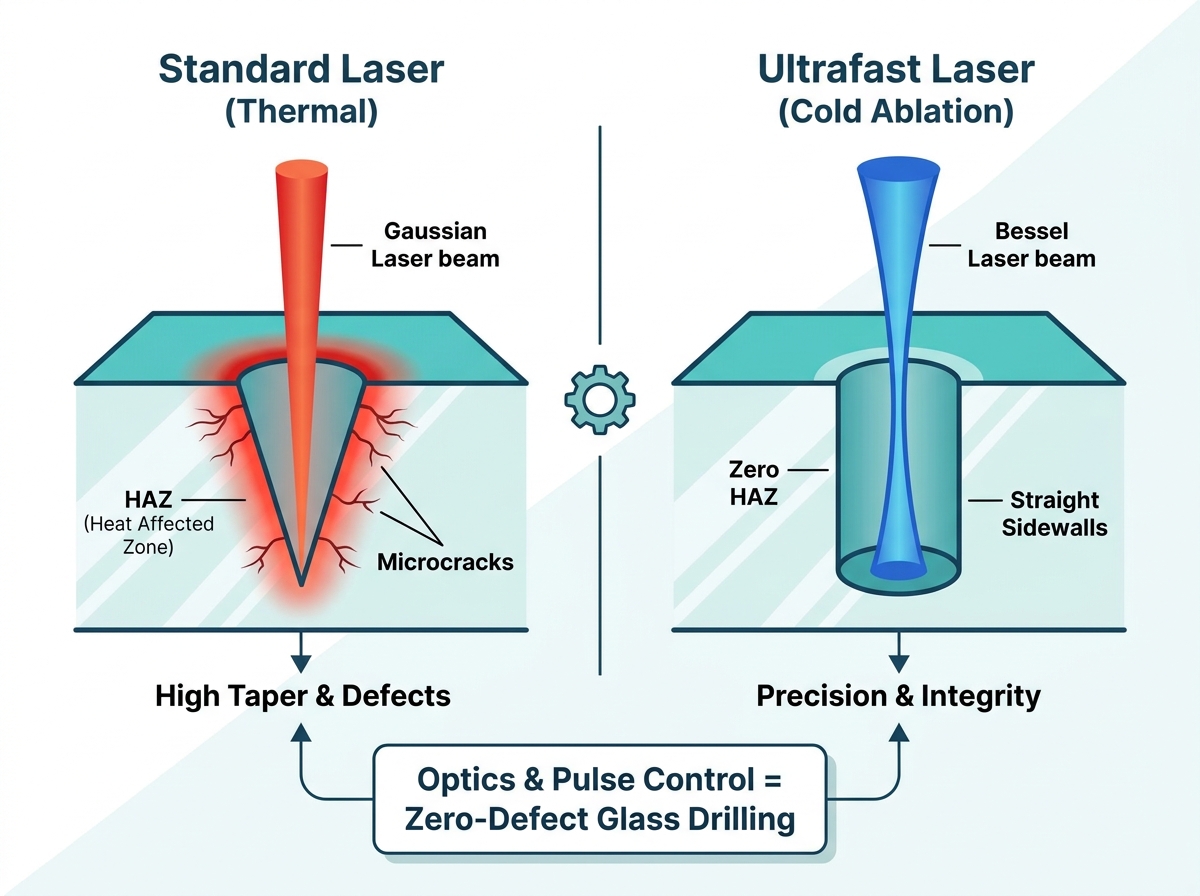
While pulse duration controls thermal damage, optics control physical geometry. Relying on basic lenses guarantees conical defects. Advanced beam shaping tools provide precise, vertical walls.
Percussion drilling fires pulses directly down a single axis. It punches straight through the substrate. This method is incredibly fast but naturally induces taper due to beam divergence. It serves well for simple venting holes.
Trepanning alters this approach. Optics steer the beam in rapid circular orbits. You progressively widen the hole from the center outward. This allows the laser to machine straight sidewalls effectively. However, trepanning significantly reduces overall throughput because the beam must travel a longer physical path.
Optical beam shaping represents a massive leap forward. Axicon lenses convert a standard Gaussian focal point into an elongated focal line. This creates a Bessel beam profile. A Bessel beam maintains its high energy density over a much longer axial distance.
This focal line penetrates the entire thickness of the substrate simultaneously. The laser modifies the full depth in a single pass. Substrates then cleave perfectly along this line. Implementing Bessel optics reduces laser drilled glass hole taper to near zero, yielding perfectly cylindrical vias.
High-aspect-ratio processing requires specific hardware. Helical drilling modules utilize specialized scan heads containing rotating prisms. These units dynamically adjust the beam's angle of incidence during processing.
By constantly shifting the entry angle, the module compensates for natural taper. The beam effectively undercuts the sidewall as it descends. This technology proves ideal for thick glass blocks or intricate nozzle components.
Equipping advanced lasers and optics only solves half the equation. Perfecting execution requires meticulous parameter tuning. Every adjustment impacts both quality and cycle time.
High pulse energy aggressively increases ablation rates. You remove material rapidly, achieving fast cycle times. However, excessive energy risks collateral acoustic damage. The shockwave from plasma expansion can mechanically shatter delicate glass structures.
Conversely, employing low pulse energy alongside high pulse overlap yields exceptionally smooth walls. You gently nibble away material instead of blasting it. This preserves structural integrity but drastically extends cycle times. Engineers must carefully balance these two forces.
Burst mode machining alters conventional pulse delivery. Instead of firing single pulses at kHz rates, the laser fires rapid bursts of pulses at MHz or GHz frequencies. The glass substrate absorbs this concentrated energy package optimally.
This technique maximizes material removal rates without inducing excess thermal stress. The ablation cooling cycle happens between bursts. It allows plasma to clear momentarily, ensuring the next burst hits fresh glass efficiently.
Vaporized glass must go somewhere. If left unmanaged, molten debris redeposits onto the cut edge. This hardened slag acts as a primary initiation site for future micro-fractures.
Best Practice: Always implement localized vacuum extraction precisely at the focal point.
Gas Selection: Use specific assist gases (like Helium or Argon) directed coaxially. They actively blow plasma away from the hole bottom.
Common Mistake: Relying solely on ambient air extraction. Cross-breezes push debris back into the fresh cut, ruining the edge finish.
Assuming your process is defect-free invites catastrophic field failures. Rigorous validation demands advanced analytical techniques. Visual checks alone remain woefully inadequate for mission-critical components.
Standard AOI systems utilize top-down camera rigs. They rapidly measure entrance and exit circularity. They easily confirm diameter accuracy against CAD models. They also flag visible surface edge chipping.
However, top-down AOI provides a false sense of security. It cannot see below the surface. A hole might appear perfectly circular from above while harboring deep internal fractures.
True quality assurance requires peering inside the substrate. Integrating cross-sectional microscopy proves essential. Technicians must physically cleave sample parts to examine the interior walls.
Confocal laser scanning microscopy provides non-destructive depth profiling. It maps the internal topography of the hole sidewall in 3D. This reveals hidden stress zones and microscopic fissures missed by standard cameras.
Visual and optical tests only tell part of the story. Implementing 4-point bend testing delivers empirical proof of success. This destructive test places precise mechanical loads on the drilled substrate until it snaps.
Engineers then perform Weibull modulus analysis on the failure data. The true test of a microcrack-free hole is whether the substrate retains its original flexural strength. Standardizing this routine ensures your laser drilling glass quality inspection aligns with real-world durability requirements.
Procuring capital equipment demands careful validation. Selecting a laser integrator based purely on marketing brochures invites severe operational risks. You must demand empirical proof.
Never procure a laser system based on spec sheets alone. Laser-material interaction varies wildly depending on exact proprietary glass compositions. Borosilicate behaves differently than Aluminosilicate.
Mandate a rigorous application lab test using your exact production material. Provide the integrator with your specific thickness and coating variations. Ask them to process a statistically significant batch of samples, not just one lucky prototype.
Thoroughly interrogate potential partners about their systemic capabilities. A good laser source fails if integrated poorly.
Do they design and provide proprietary beam shaping optics in-house?
Can they seamlessly integrate inline AOI modules directly into the motion stage?
What is their promised maintenance interval and uptime guarantee for complex helical drilling heads?
Do they offer local field service engineers familiar with ultrafast optical alignments?
Eliminating microcracks and hole taper requires more than buying a newer laser. It demands a holistic alignment of ultrafast pulse durations, advanced optical shaping like Bessel lenses, and rigorous parameter tuning. Ignoring any single variable invites hidden defects back into your workflow.
Decision-makers must shift their focus away from raw processing speed. Prioritize first-pass yield and preserved flexural strength. Engage exclusively with integrators who offer transparent lab testing. Validate their claims through destructive mechanical validation. By adopting these exact frameworks, your production floor can finally achieve zero-defect glass processing.
A: Generally, no. Thermal lasers rely on melting and rapid expansion, which inherently produces a large Heat Affected Zone (HAZ). This thermal stress inevitably causes micro-fractures in rigid glass. To use these systems successfully, you must implement post-process chemical etching. Acid baths dissolve the damaged surface layers, removing the fractures and restoring baseline structural integrity.
A: Standard Bessel beam optics perform exceptionally well up to approximately 3mm to 5mm thicknesses, maintaining near-zero taper. Beyond this depth, the Rayleigh length limitations of the optics reduce beam intensity. For high-aspect-ratio holes exceeding 5mm, manufacturers must switch to specialized helical drilling modules. These dynamically adjust the beam angle to counteract deep taper.
A: Different glass types feature unique bandgaps, thermal expansion coefficients, and optical transmission rates. For example, Borosilicate and Aluminosilicate absorb photon energy differently. You must adjust laser wavelength, pulse energy, and burst repetition rates accordingly. Failing to tune parameters to your specific chemical composition leads to inefficient energy absorption, causing excess heat accumulation and subsequent fractures.
A: Attempting to drill already tempered glass carries a severe risk of catastrophic shattering. The tempering process locks massive compressive stress into the outer layers and tensile stress into the core. Piercing this tension zone usually shatters the entire panel instantly. Manufacturers almost exclusively perform laser drilling and edge cutting prior to the chemical strengthening process.
